Hardware Products
Open-source IoT sensors for groundwater monitoring. Solar-powered, LoRa/cellular connected, built for the field.
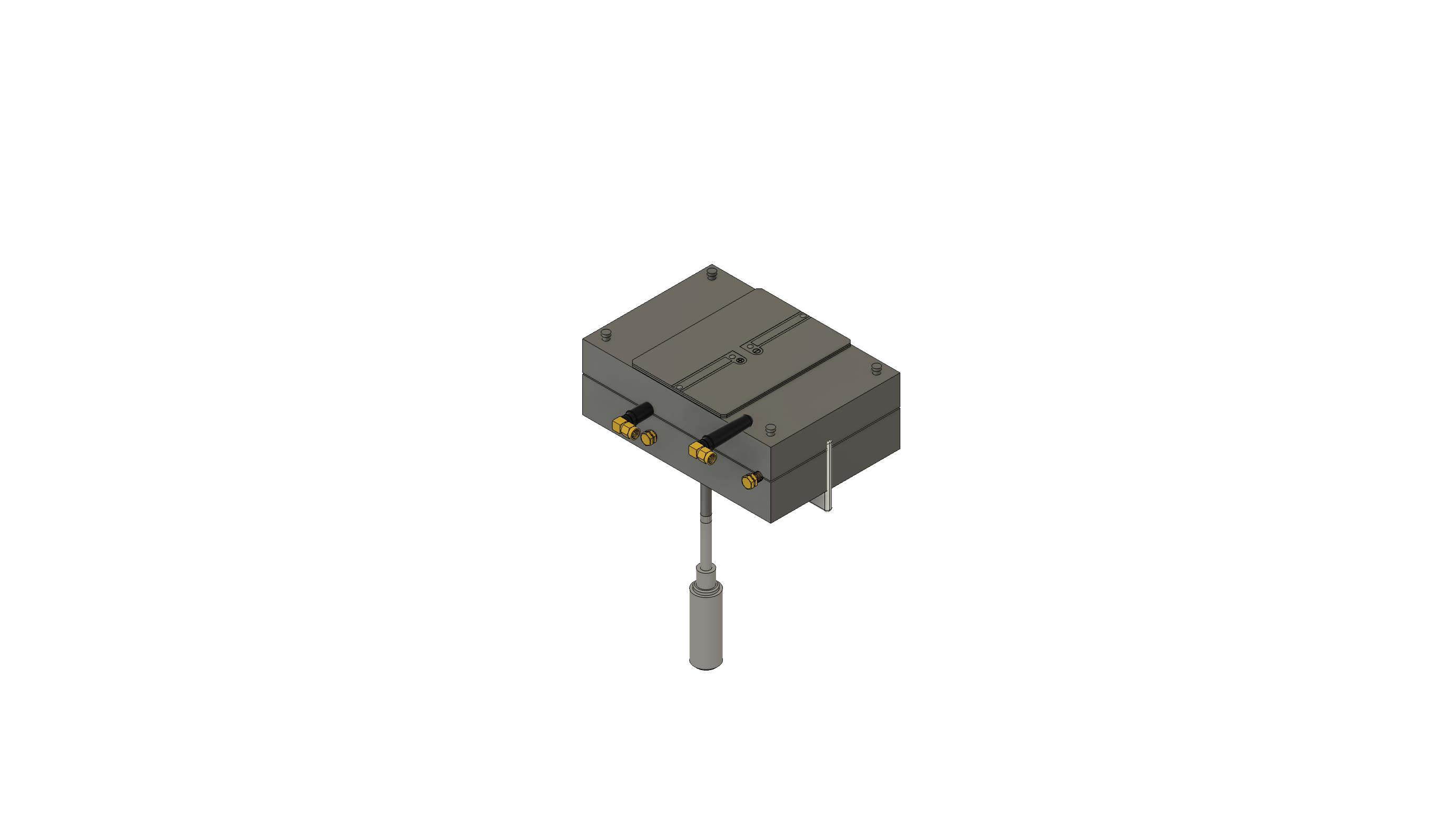
Smart Well Level Meter
WX-Level
Continuous groundwater level monitoring
Submersible pressure transducer paired with a solar-powered ESP32 controller. Mounts on any monitoring or irrigation well and transmits water level, temperature, and battery status every 15 minutes via LoRa or cellular.
Key Specifications
Measurement
Water Level
Pressure-based, 0–100 ft range
Accuracy
±0.1 ft
0.1% FS, temperature compensated
Connectivity
LoRa + Cellular
SX1276 915MHz + SIM7000G
Power
Solar + LiPo
6W panel, 6000mAh battery
Battery Life
Indefinite
30+ days without sun
Enclosure
IP67
3D-printed PETG + gasket
MCU
ESP32-S3
Deep sleep: 10 µA
Target BOM
~$85
At qty 100
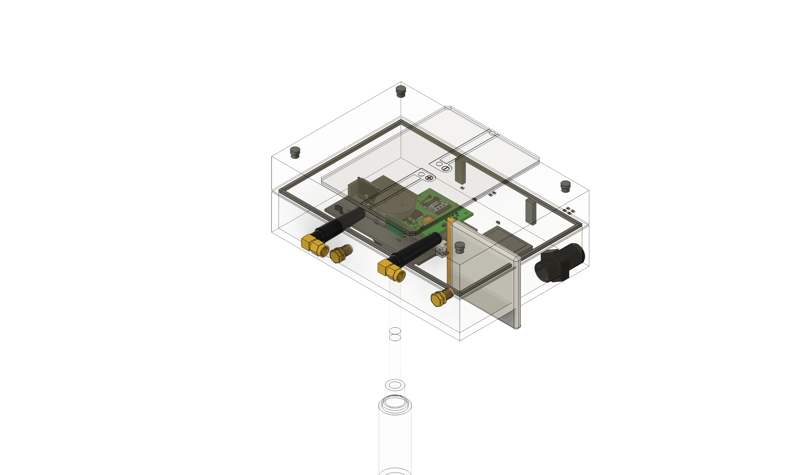
Inside the Controller
What's inside
ESP32-S3 microcontroller, ADS1115 16-bit ADC, BME280 barometric sensor, LoRa and cellular modules, CN3791 solar MPPT charger, and a 6000mAh LiPo battery — all on a compact 80×50mm PCB.